10 Fundamental and Motivation of Pipelining
10.1 The Motivation
10.1.1 What is disadvantages of the single-cycle design?
- Critical Path is too long
- Low maximum clock frequency
- Not compatible with non-ideal memory where the access latency is not zero
The overriding motivation for pipelining is to raise the maximum clock frequency: because the clock period is ultimately set by the critical path period, breaking the work into stages shortens that delay per stage and lets the design run faster.
10.2 The Fundamental
10.2.1 How to shorten the critical path?
What is the essence of pipeline design?
Visualization of pipeline design
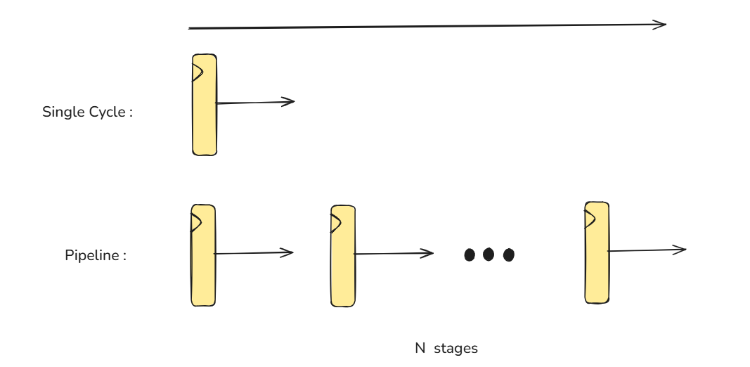
Picture a CPU as a water pipe: single-cycle is one long pipe where the slowest section sets the pace, while pipelining slices it with “tanks” so packets flow concurrently—shortening per-stage delay and raising the maximum clock frequency.
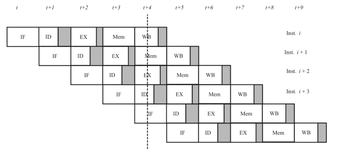
The micro-architecture of a classic five stages pipeline CPU
A classic 5-stage pipeline (IF, ID, EX, MEM, WB) is spread across clock cycles, and each stage takes exactly one clock. An instruction needs 5 cycles of latency to pass all stages, but once the pipe is full, a new instruction completes every clock.
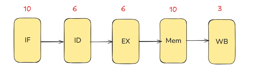
This figure is from [1] Focusing on the datapath: before pipelining, a
LOADgoes through 10+6+6+10+3 = 35 units of delay, so the overall critical path is 35. With one instruction completed per clock, the clock period must be ≥ 35.The latency caused by inserting the register is ignored here. A more detailed explanation of how to calculate the impact of latency will be provided later.
With pipelining, we choose the clock period to match the slowest stage—in this case, MEM. That makes the per-stage critical path 10, so the design can run with a 10-unit clock period, ignoring pipeline-register overhead.
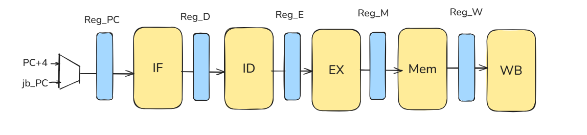
abstracted pipeline
10.2.2 What is the problem about pipeline CPU?
What’s the catch with a pipelined CPU? Hazards introduce pipeline bubbles, which lower the instructions-per-cycle (IPC). And even if you pipeline, if the core is scalar rather than superscalar, the ideal maximum IPC is still 1—this point is crucial.
In a pipelined CPU, hazards (data and control) can make one stage interfere with the next.So we put pipeline registers between every stage to latch results each clock.These registers give clear 1-cycle boundaries and let us stall, insert bubbles, or flush safely—and support forwarding for dependencies.
Result: hazards are controlled and the pipeline can run at the chosen stage period.
Structural Hazard (resource contention)
Problem : Hardware resources are not enough.
Problem in Pipeline CPU : Accessing memory at the same time by fetching instructions and loading data.
Solution : We duplicate SRAM as im & dm to solve memory access problem of simultaneous instruction fetch and load data.
Control Hazard
Problem : There is an indeterminate instruction flow in the pipeline.
Problem in Pipeline CPU : The subsequent instructions have entered the pipeline before the jump or branch is determined.
Solution : We implement a
flushsignal in the Controller to flush the wrong instructions in pipeline registers.Jump and Branch Instructions with pipeline CPU
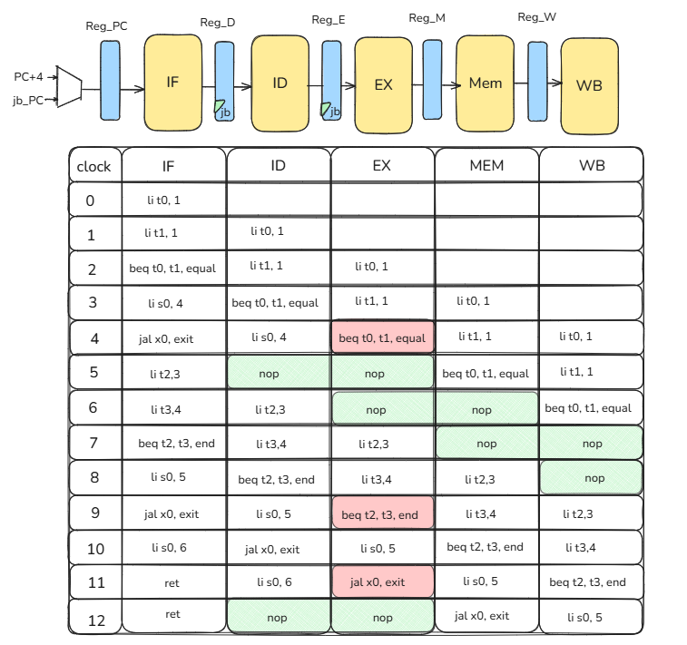
Below is an example of a control hazard caused by jump and branch instructions; the instruction sequence is as follows.
PC instructions explanation 0 li t0, 1 t0 = 1 4 li t1, 1 t1 = 1 8 beq t0, t1, equal 1 == 1 branch taken to equal c li s0, 4 skipped 10 jal x0, exit skipped equal:14 li t2, 3 t2 = 3 18 li t3, 4 t3 = 4 1c beq t2, t3, end 3 == 4? No, branch not taken 20 li s0, 5 s0 = 5 24 jal x0, exit jump to exit end:28 li s0, 6 skipped exit:2c ret return to caller In this design, the branch outcome is known in EX. If the branch is taken, then on the next clock we must flush the ID and EX stages and insert a NOP
addi x0, x0, 0so nothing executes. Therefore, reg_D and reg_E must accept the jb (jump/branch) signal as a flush input, and the IF stage must load jb_pc as the next PC.Below is what each stage does in each clock cycle.
jb control hazard
TipBranch PredictionBranch prediction is also a form of control hazard. In Lab 4 we’ll introduce only the concept later.
There is no specific solution. In the Lab 4 report, you will be asked to briefly describe how you would design the control signals to resolve this hazard.
Data Hazard
Problem : Unable to get the latest data for calculations.
Problem in Pipeline CPU : If the result data of an instruction needs to be writeback, subsequent instructions cannot get it until it completes.The root cause is the limited number of architectural registers.
Solution : We forwards the writeback data from MEM stage & WB stage to ID stage & EX stage
3 types of data hazards
Read-After-Write (true dependency)
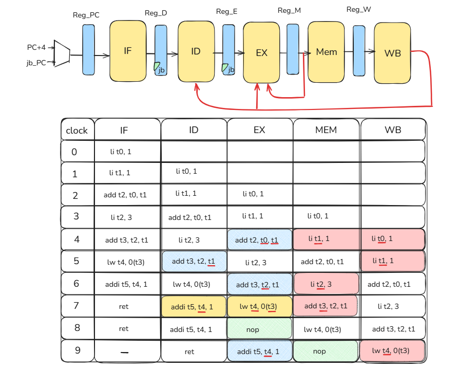
Below is an example of a Read-After-Write hazard; the instruction sequence is as follows.
PC instructions explanation 0 li t0, 1 t0 = 1 4 li t1, 1 t1 = 1 8 add t2, t0, t1 t2 = t0 + t1 c li t2, 3 t2 = 3 10 add t3, t2, t1 t3 = t2 + t1 14 lw t4, 0(t3) Load a word at address t3 + 0 into t4 18 addi t5, t4, 1 t5 = t4 + 1 1c ret return to caller add t2,t0,t1depends onli t0,1andli t1,1(resolved by forwarding).add t3,t2,t1depends onli t2,3(also resolved by forwarding).addi t5,t4,1immediately afterlw t4,0(t3), the load’s data isn’t ready until the MEM/WB boundary, so this pair needs a 1-cycle stall even with forwarding.Below is what each stage does in each clock cycle.
RAW data hazard Write-After-Read (anti-dependency)
Below is an example of a Write-After-Read hazard; the instruction sequence is as follows.
PC instructions explanation 0 add t2, t1, t3 t2 = t1 + t3 4 li t1, 5 t1 = 5 WAR hazard occurs when an earlier instruction must read a register (or memory location) before a later instruction writes that same name. The hazard is: if the later write happens too early, the earlier read could see the wrong (new) value.
If I2 writes t1 before I1 has read it, that’s a WAR hazard.
In a classic 5-stage, single-issue, in-order pipeline (in Lab4), WAR doesn’t occur because reads happen in ID, writes happen in WB, and everything retires in program order. A younger instruction can’t write before an older one has already read. Hence, register WAR needs no stalls or forwarding here; it shows up only with out-of-order/multi-issue designs or with memory reordering.
Write-After-Write (output dependency)
Below is an example of a Write-After-Write hazard; the instruction sequence is as follows.
PC instructions explanation 0 li t1, 5 t1 = 5 4 addi t1, t1,1 t1 = t1 + 1 WAW hazard occurs when two instructions write the same destination; the hazard is that the younger write could reach the writeback point before the older write, corrupting the intended final value/order.
If I2 were to write t1 before I1, that’s a WAW hazard.
In a classic 5-stage, single-issue, in-order pipeline (in Lab4), WAW doesn’t occur because all writes happen in WB and instructions retire strictly in program order. A younger instruction cannot reach WB before the older one, so WAW cannot arise (no stalls/forwarding needed). WAW shows up in out-of-order or superscalar designs, where multiple instructions can progress and write out of order unless renaming enforces unique physical destinations.
NoteIn essence, anti-dependencies and output dependencies stem from the ISA’s limited set of architectural registers. By providing more physical registers and using register renaming, we can eliminate these constraints and enable out-of-order execution.
TipDiminishing returnsAs you add more pipeline stages, the forwarding/bypass network grows rapidly (roughly with depth and width), adding long wires and big muxes that eat into the clock gains—classic diminishing returns.
Deeper pipelines also amplify branch penalties and expose memory latency, so IPC doesn’t rise proportionally. A simple alternative is a fully-stall policy: omit long-distance bypasses and insert bubbles until the producer value is written back—less hardware, easier timing, predictable behavior (at the cost of higher CPI).
Load-Use Hazard (Special Case)
Fundamentally, it’s about memory latency: if you force the pipeline to wait for each memory request to complete, you lengthen the critical path and drag down overall performance—so even with a higher IPC, the machine can end up slower.
This is a good reminder that in quantitative analysis we must avoid the pitfall of optimizing for a single metric.