2 Introduction to RISC-V ISA
Before reading the document below, you may first refer to the following two slides which contain explanatory videos as well. The two slides can be downloaded via the links, and the video links are provided on the first page of each slide.
These teaching materials were prepared by the former Head TA, Bo-Wei Lin, who is currently pursuing his Ph.D. in Electrical Engineering at National Cheng Kung University.
If you are interested in how RISC-V is developed and the art of RISC-V, you can read the book [1].
In this lecture, it only covers the unprivileged architecture of RISC-V ISA, while there are privileged architecture in addition. For more information about priv. architecture, please refer to the specification of privileged architecture [2].
2.1 The Software/Hardware Interface - ISA
As stated in Chapter 1, the ISA serves as the interface between software and hardware. The term “interface” here represents a level of abstraction. In other words, software developers do not need to understand the low-level details of hardware implementation as long as the ISA requirements are satisfied. Similarly, hardware designers do not need to fully understand the complexities of the software stack, as long as the hardware correctly supports the ISA.
This abstraction allows both sides to evolve independently: new hardware implementations can be developed without requiring changes to existing software, and new software can run on different generations of hardware, provided they share the same ISA. Only when performance considerations or specialized optimizations are involved does a deeper cross-layer understanding become necessary.
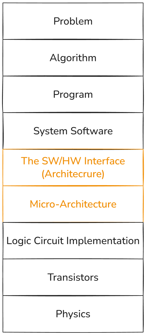
Note: When we talk about Architecture in this context, we are referring to the Instruction Set Architecture (ISA). By contrast, when discussing Micro-architecture, the term refers to the hardware implementation details of a processor or other hardware.
We can solve any problem by introducing an extra level of indirection (abstraction layer).
— The fundamental theorem of software engineering (FTSE)
2.2 Introduction to RISC-V
RISC-V (pronounced “risk-five”) is a new instruction-set architecture (ISA) that was originally designed to support computer architecture research and education, but which we now hope will also become a standard free and open architecture for industry implementations. Our goals in defining RISC-V include:
- A completely open ISA that is freely available to academia and industry.
- A real ISA suitable for direct native hardware implementation, not just simulation or binary translation.
- An ISA that avoids “over-architecting” for a particular microarchitecture style (e.g., microcoded, in- order, decoupled, out-of-order) or implementation technology (e.g., full-custom, ASIC, FPGA), but which allows efficient implementation in any of these.
- An ISA separated into a small base integer ISA, usable by itself as a base for customized accelerators or for educational purposes, and optional standard extensions, to support general- purpose software development.
- Support for the revised 2008 IEEE-754 floating-point standard.
- An ISA supporting extensive ISA extensions and specialized variants.
- Both 32-bit and 64-bit address space variants for applications, operating system kernels, and hardware implementations.
- An ISA with support for highly parallel multicore or manycore implementations, including heterogeneous multiprocessors.
- Optional variable-length instructions to both expand available instruction encoding space and to support an optional dense instruction encoding for improved performance, static code size, and energy efficiency.
- A fully virtualizable ISA to ease hypervisor development.
- An ISA that simplifies experiments with new privileged architecture designs.
The RISC-V ISA is defined avoiding implementation details as much as possible (although commentary is included on implementation-driven decisions) and should be read as the software-visible interface to a wide variety of implementations rather than as the design of a particular hardware artifact.
The RISC-V manual is structured in two volumes. This volume covers the design of the base unprivileged instructions, including optional unprivileged ISA extensions. Unprivileged instructions are those that are generally usable in all privilege modes in all privileged architectures, though behavior might vary depending on privilege mode and privilege architecture. The second volume provides the design of the first (“classic”) privileged architecture. The manuals use IEC 80000-13:2008 conventions, with a byte of 8 bits.
— From Chapter 1 in RISC-V ISA Spec Volume I [3]
2.2.1 RISC-V ISA Overview
A RISC-V ISA is defined as a base integer ISA, which must be present in any implementation, plus optional extensions to the base ISA. The base integer ISAs are very similar to that of the early RISC processors except with no branch delay slots and with support for optional variable-length instruction encodings. A base is carefully restricted to a minimal set of instructions sufficient to provide a reasonable target for compilers, assemblers, linkers, and operating systems (with additional privileged operations), and so provides a convenient ISA and software toolchain “skeleton” around which more customized processor ISAs can be built.
Although it is convenient to speak of the RISC-V ISA, RISC-V is actually a family of related ISAs, of which there are currently four base ISAs. Each base integer instruction set is characterized by the width of the integer registers and the corresponding size of the address space and by the number of integer registers. There are two primary base integer variants, RV32I and RV64I, described in Chapter 2 and Chapter 4, which provide 32-bit or 64-bit address spaces respectively. We use the term XLEN to refer to the width of an integer register in bits (either 32 or 64). Chapter 3 describes the RV32E and RV64E subset variants of the RV32I or RV64I base instruction sets respectively, which have been added to support small microcontrollers, and which have half the number of integer registers. The base integer instruction sets use a two’s-complement representation for signed integer values.
RISC-V has been designed to support extensive customization and specialization. Each base integer ISA can be extended with one or more optional instruction-set extensions. An extension may be categorized as either standard, custom, or non-conforming. For this purpose, we divide each RISC-V instruction-set encoding space (and related encoding spaces such as the CSRs) into three disjoint categories: standard, reserved, and custom. Standard extensions and encodings are defined by RISC-V International; any extensions not defined by RISC-V International are non-standard. Each base ISA and its standard extensions use only standard encodings, and shall not conflict with each other in their uses of these encodings. Reserved encodings are currently not defined but are saved for future standard extensions; once thus used, they become standard encodings. Custom encodings shall never be used for standard extensions and are made available for vendor-specific non-standard extensions. Non-standard extensions are either custom extensions, that use only custom encodings, or non- conforming extensions, that use any standard or reserved encoding. Instruction-set extensions are generally shared but may provide slightly different functionality depending on the base ISA. Chapter 36 describes various ways of extending the RISC-V ISA. We have also developed a naming convention for RISC-V base instructions and instruction-set extensions, described in detail in Chapter 37.
To support more general software development, a set of standard extensions are defined to provide integer multiply/divide, atomic operations, and single and double-precision floating-point arithmetic. The base integer ISA is named “I” (prefixed by RV32 or RV64 depending on integer register width), and contains integer computational instructions, integer loads, integer stores, and control-flow instructions. The standard integer multiplication and division extension is named “M”, and adds instructions to multiply and divide values held in the integer registers. The standard atomic instruction extension, denoted by “A”, adds instructions that atomically read, modify, and write memory for inter- processor synchronization. The standard single-precision floating-point extension, denoted by “F”, adds floating-point registers, single-precision computational instructions, and single-precision loads and stores. The standard double-precision floating-point extension, denoted by “D”, expands the floating-point registers, and adds double-precision computational instructions, loads, and stores. The standard “C” compressed instruction extension provides narrower 16-bit forms of common instructions.
Beyond the base integer ISA and these standard extensions, we believe it is rare that a new instruction will provide a significant benefit for all applications, although it may be very beneficial for a certain domain. As energy efficiency concerns are forcing greater specialization, we believe it is important to simplify the required portion of an ISA specification. Whereas other architectures usually treat their ISA as a single entity, which changes to a new version as instructions are added over time, RISC-V will endeavor to keep the base and each standard extension constant over time, and instead layer new instructions as further optional extensions. For example, the base integer ISAs will continue as fully supported standalone ISAs, regardless of any subsequent extensions.
From Chapter 1.4 in RISC-V ISA Spec Volume I [3]
2.3 Architectural Registers for Base Integer Instruction Set
Registers are the most important part for almost any processor. More precisely, the architectural register are the most important component inside a processor which records the current states of the processor. In RISC-V base integer set, there are 32 general purpose registers, which are used for any purpose. However, the register x0 should always be zero according the the ISA specification [3]. In addition, there is one special register which is called Program Counter or PC for short. The duty of PC is to record the memory address of the current instruction to be executed.
Here is the list of all 32 general purpose registers:
| Register | ABI | Use by convention | Preserved? |
|---|---|---|---|
| x0 | zero | hardwired to 0, ignores writes | n/a |
| x1 | ra | return address for jumps | no |
| x2 | sp | stack pointer | yes |
| x3 | gp | global pointer | n/a |
| x4 | tp | thread pointer | n/a |
| x5 | t0 | temporary register 0 | no |
| x6 | t1 | temporary register 1 | no |
| x7 | t2 | temporary register 2 | no |
| x8 | s0 or fp | saved register 0 or frame pointer | yes |
| x9 | s1 | saved register 1 | yes |
| x10 | a0 | return value or function argument 0 | no |
| x11 | a1 | return value or function argument 1 | no |
| x12 | a2 | function argument 2 | no |
| x13 | a3 | function argument 3 | no |
| x14 | a4 | function argument 4 | no |
| x15 | a5 | function argument 5 | no |
| x16 | a6 | function argument 6 | no |
| x17 | a7 | function argument 7 | no |
| x18 | s2 | saved register 2 | yes |
| x19 | s3 | saved register 3 | yes |
| x20 | s4 | saved register 4 | yes |
| x21 | s5 | saved register 5 | yes |
| x22 | s6 | saved register 6 | yes |
| x23 | s7 | saved register 7 | yes |
| x24 | s8 | saved register 8 | yes |
| x25 | s9 | saved register 9 | yes |
| x26 | s10 | saved register 10 | yes |
| x27 | s11 | saved register 11 | yes |
| x28 | t3 | temporary register 3 | no |
| x29 | t4 | temporary register 4 | no |
| x30 | t5 | temporary register 5 | no |
| x31 | t6 | temporary register 6 | no |
| pc | (none) | program counter | n/a |
In order to implement the simulator which can simulate a RISC-V machine, the simulator must implement these registers inside.
You might note that there are two special columns in the table called ABI and Preserved. These entries are related to the concepts of Application binary Interface (ABI). The introduction to ABI will be placed at the Section 5.4.2, and we will skip this part at the moment.
2.4 RISC-V Instruction Encoding Formats
When it comes to ISA instructions, the encoding for the instruction is always the first aspect to address. The way an instruction is encoded has a significant impact on how a processor is designed, particularly for the instruction decoder. Similarly, it affects how we implement the decode logic when building the ISA simulator. Therefore, getting familiar with RISC-V instruction formats is one of the essential tasks.
In RISC-V, there are four base instruction formats and two extended formats. The additional two formats are mainly related to the handling of immediates.
2.4.1 Base Instruction Format


R-Type and I-Type are two of the four base instruction formats which do not have extended format. Besides, there are two formats S-Type and U-Type which have extended formats. The extended formats for S-Type and U-Type are B-Type and J-Type respectively.


According to the RISC-V specification for unprivileged architecture [3]:
The RISC-V ISA keeps the source (rs1 and rs2) and destination (rd) registers at the same position in all formats to simplify decoding.
Except for the 5-bit immediates used in CSR instructions (Chapter 6), immediates are always sign-extended, and are generally packed towards the leftmost available bits in the instruction and have been allocated to reduce hardware complexity.
In particular, the sign bit for all immediates is always in bit 31 of the instruction to speed sign-extension circuitry.
We could find some important properties:
- The source (rs1 and rs2) and destination (rd) registers are at the same position in all formats (except for CSR instructions)
- Immediates are always sign-extended before performing arithmetic operations
- The sign bit for all immediates is always in bit 31 of the instruction
These great ideas greatly reduce the hardware complexity of designing an instruction decoder inside a real RISC-V processor.
2.4.2 Immediate Encoding Variants

As what we just said, there are two extended instruction format B-Type and J-Type. The B-Type format is based on S-Type format, while how the immediates are encoded is different. According to [3]:
The only difference between the S and B formats is that the 12-bit immediate field is used to encode branch offsets in multiples of 2 in the B format. Instead of shifting all bits in the instruction-encoded immediate left by one in hardware as is conventionally done, the middle bits (imm[10:1]) and sign bit stay in fixed positions, while the lowest bit in S format (inst[7]) encodes a high-order bit in B format.

Similarly, J-Type format is based on U-Type format. According to [3]:
Similarly, the only difference between the U and J formats is that the 20-bit immediate is shifted left by 12 bits to form U immediates and by 1 bit to rorm J immediates. The location of instruction bits in the U and J format immediates is chosen to maximize overlap with the other formats and with each other.
Let’s look these different immediates in another point of view:
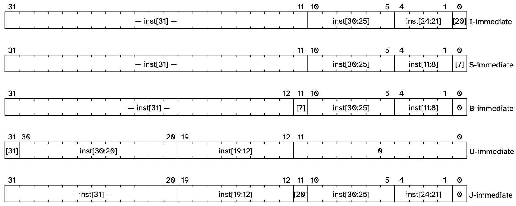
According to the statements in [3]:
Immediate types shows the immediates produced by each of the base instruction formats, and is labeled to show which instruction bit (inst[y]) produces each bit of the immediate value. The fields are labeled with the instruction bits used to construct their value. Sign extensions always uses inst[31].
2.5 RV32I Instructions
We can divide instructions in RV32I base integer instruction set into several parts, including:
- integer computational instructions
- control transfer instructions
- load and store instructions
- memory ordering instructions
- environment call and breakpoint instructions.
However, we do not cover 4. and 5. in this lab.
Before we go into the details about each instruction, let’s take a look on opcode map:
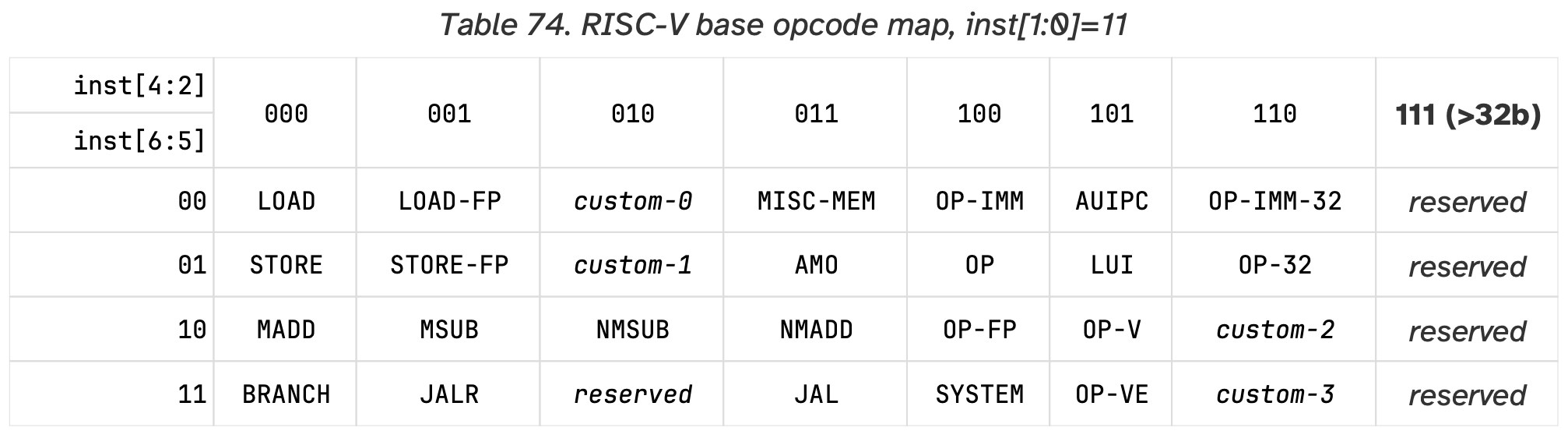
For those instructions we must implement in the ISA Simulator, we have to recognize the following opcodes:
- OP
- Register-Register Operations
- OP-IMM
- Register-Immediate Operations
- LOAD
- Load Operations
- STORE
- Store Operations
- BRANCH
- Conditional Branches
- JAL
- Only for JAL instruction, which is Unconditional Jump
- JALR
- Only for JALR instruction, which is Unconditional Jump
- LUI
- Only for LUI instruction
- AUIPC
- Only for AUIPC instruction
All the 37 instructions we must implement all belong to one of these opcodes. Let’s talk about these 37 instructions in the perspective of their functionality.
2.5.1 Integer Computational Instructions
Integer Register-Immediate Operations

ADDI adds the sign-extended 12-bit immediate to register rs1. Arithmetic overflow is ignored and the result is simply the low XLEN bits of the result. ADDI rd, rs1, 0 is used to implement the MV rd, rs1 assembler pseudoinstruction.
SLTI (set less than immediate) places the value 1 in register rd if register rs1 is less than the sign-extended immediate when both are treated as signed numbers, else 0 is written to rd. SLTIU is similar but compares the values as unsigned numbers (i.e., the immediate is first sign-extended to XLEN bits then treated as an unsigned number). Note, SLTIU rd, rs1, 1 sets rd to 1 if rs1 equals zero, otherwise sets rd to 0 (assembler pseudoinstruction SEQZ rd, rs).
ANDI, ORI, XORI are logical operations that perform bitwise AND, OR, and XOR on register rs1 and the sign-extended 12-bit immediate and place the result in rd. Note, XORI rd, rs1, -1 performs a bitwise logical inversion of register rs1 (assembler pseudoinstruction NOT rd, rs).
— From Chapter 2.4.1 in RISC-V ISA Spec [3]
The first class of OP-IMM instructions are the general arithmetic instructions which perform common operations such as addition, logical operations and conditional set operation.
Without conditional set instructions, some types of C code might be generated in more complex fashion. For example, consider the following segment of C code:
It can be translated into the assembly code below with SLT instruction (a is stored in x1, and b is stoted in x2):
You can find that there is no any branch instruction needed even with if-else statement in the C code above.

Shifts by a constant are encoded as a specialization of the I-type format. The operand to be shifted is in rs1, and the shift amount is encoded in the lower 5 bits of the I-immediate field. The right shift type is encoded in bit 30. SLLI is a logical left shift (zeros are shifted into the lower bits); SRLI is a logical right shift (zeros are shifted into the upper bits); and SRAI is an arithmetic right shift (the original sign bit is copied into the vacated upper bits).
— From Chapter 2.4.1 in RISC-V ISA Spec [3]
The second class of OP-IMM instructions are related to shift operations, including shift-right-logically, shift-right-arithmetically, and shift-left-logically.

Third class of OP-IMM instructions are LUI and AUIPC instructions.
LUI (load upper immediate) is used to build 32-bit constants and uses the U-type format. LUI places the 32-bit U-immediate value into the destination register rd, filling in the lowest 12 bits with zeros.
AUIPC (add upper immediate to pc) is used to build pc-relative addresses and uses the U-type format. AUIPC forms a 32-bit offset from the U-immediate, filling in the lowest 12 bits with zeros, adds this offset to the address of the AUIPC instruction, then places the result in register rd.
— From Chapter 2.4.1 in RISC-V ISA Spec [3]
LUI and AUIPC are often used for data accessing and PC jump operations, which will be introduced in Chapter 5.
Integer Register-Register Operations

NOP Instruction

Instead of being a new instruction, the NOP (No-operation) instruction is encoded as ADDI x0, x0, 0. NOP instruction will not change any architectural visible state, except for advancing the PC and some other related performance counters.
2.5.2 Control Transfer Instructions
Unconditional Jumps


There are two instructions perform unconditional jump operation: JAL and JALR. JAL is used to perform the unconditional jump with PC + imm as the target address, while the jump target of JALR instruction is rs1 + imm. The main difference is about the jump offset. For JAL, the jump offset is \(\pm 1 \text{MiB}\). However, for a 32-bit processor, the pair of LUI and JALR can be used to jump to any memory address. (We will introduce it in more detail in Chapter 5)
The jump and link (JAL) instruction uses the J-type format, where the J-immediate encodes a signed offset in multiples of 2 bytes. The offset is sign-extended and added to the address of the jump instruction to form the jump target address. Jumps can therefore target a ±1 MiB range. JAL stores the address of the instruction following the jump (‘pc’+4) into register rd. The standard software calling convention uses ‘x1’ as the return address register and ‘x5’ as an alternate link register.
Plain unconditional jumps (assembler pseudoinstruction J) are encoded as a JAL with rd=x0.
The indirect jump instruction JALR (jump and link register) uses the I-type encoding. The target address is obtained by adding the sign-extended 12-bit I-immediate to the register rs1, then setting the least-significant bit of the result to zero. The address of the instruction following the jump (pc+4) is written to register rd. Register x0 can be used as the destination if the result is not required.
Plain unconditional indirect jumps (assembler pseudoinstruction JR) are encoded as a JALR with rd= x0. Procedure returns in the standard calling convention (assembler pseudoinstruction RET) are encoded as a JALR with rd=x0, rs1=x1, and imm=0.
From Chapter 2.5.1 in RISC-V Spec Volume I [3]
Furthermore, the encoding of immediate for JAL is also different from JALR. For JAL, the imm[0] is omitted in order to ensure that the jump offset is always 2-byte aligned.
Why is the alignment requirement of jump offset is 2 instead of 4?
Hint: RISC-V C-Extension
Conditional Branches

In base integer instruction set, there are six instructions to perform conditional branch operations. Similarly, the imm[0] in BRANCH instructions is also omitted.
2.5.3 Load and Store Instructions


For load and store instructions, the most important parameter for these instruction is the width, and there are five load instructions and three instructions respectively in RV32I.
RV32I is a load-store architecture, where only load and store instructions access memory and arithmetic instructions only operate on CPU registers. RV32I provides a 32-bit address space that is byte-addressed. The EEI will define what portions of the address space are legal to access with which instruction (e.g., some addresses might be read only, or support word access only). Loads with a destination of x0 must still raise any exceptions and cause any other side effects even though the load value is discarded.
The EEI will define whether the memory system is little-endian or big-endian. In RISC-V, endianness is byte-address invariant.
The LW instruction loads a 32-bit value from memory into rd. LH loads a 16-bit value from memory, then sign-extends to 32-bits before storing in rd. LHU loads a 16-bit value from memory but then zero extends to 32-bits before storing in rd. LB and LBU are defined analogously for 8-bit values. The SW, SH, and SB instructions store 32-bit, 16-bit, and 8-bit values from the low bits of register rs2 to memory.
— From Chapter 2.6 in RISC-V ISA Spec Volume 1 [3]
What is the reason that there are no SBU (store-byte-unsigned) and SHU (store-half-word-unsigned) instructions?
Hint: Do we actually need these instructions?
2.6 RV32I Instruction List
- For a given number (or register)
A, it is unsigned number if it is annotated asunsigned(A). Otherwise, it is signed number. - We can extract part of bits via the annotation
A[lsb_position:msb_position]. For example, we can extract bit 5 to bit 20 of a number A viaA[5:20]. - We can use the following two annotations to expand the bit-width of the numbers which are less than 32-bit width to 32-bits.
signed_extend(A), which performs signed-extension.zero_extend(A), which performs zero-extension.
- For annotating immediates, there are the convention is that:
- When we write
imm, it indicates the immediate is signed-extended to 32-bits. - When we write
unsigned(imm), it indicates the original immediate is zero-extended to 32-bits.
- When we write
The granularity of accessing to the mmeory is a word (i.e., 32-bits) at here. For example, the annotation M[0x200] indicates four bytes of data starts from the memory address 0x200 to 0x204.
| Instruction Name | Opcode Map | Semantics (Described in Pseudocode) |
|---|---|---|
| LUI | LUI | rd = imm << 12 |
| AUIPC | AUIPC | rd = PC + (imm << 12) |
| JAL | JAL | rd = PC + 4 PC += imm |
| JALR | JALR | rd = PC + 4 PC = rs1 + imm PC[0] = 0 |
| BEQ | BRANCH | if(rs1 == rs2) PC += imm |
| BNE | BRANCH | if(rs1 != rs2) PC += imm |
| BLT | BRANCH | if(rs1 < rs2) PC += imm |
| BGE | BRANCH | if(rs1 >= rs2) PC += imm |
| BLTU | BRANCH | if(unsigned(rs1) < unsigned(rs2)) PC += imm |
| BGEU | BRANCH | if(unsigned(rs1) >= unsigned(rs2)) PC += imm |
| LB | LOAD | rd = signed_extend(M[rs1+imm][0:7]) |
| LH | LOAD | rd = signed_extend(M[rs1+imm][0:15]) |
| LW | LOAD | rd = M[rs1+imm][0:31] |
| LBU | LOAD | rd = zero_extend(M[rs1+imm][0:7]) |
| LHU | LOAD | rd = zero_extend(M[rs1+imm][0:15]) |
| SB | STORE | M[rs1+imm][0:7] = rs2[0:7] |
| SH | STORE | M[rs1+imm][0:15] = rs2[0:15] |
| SW | STORE | M[rs1+imm][0:31] = rs2[0:31] |
| ADDI | OP-IMM | rd = rs1 + imm |
| SLTI | OP-IMM | rd = (rs1 < imm) ? 1 : 0 |
| SLTIU | OP-IMM | rd = (unsigned(rs1) < unsigned(imm)) ? 1 : 0 |
| XORI | OP-IMM | rd = rs1 ^ imm |
| ORI | OP-IMM | rd = rs1 | imm |
| ANDI | OP-IMM | rd = rs1 & imm |
| SLLI | OP-IMM | rd = rs1 << imm[4:0] |
| SRLI | OP-IMM | rd = unsigned(rs1) >> imm[4:0] |
| SRAI | OP-IMM | rd = rs1 >> imm[4:0] |
| ADD | OP | rd = rs1 + rs2 |
| SUB | OP | rd = rs1 - rs2 |
| SLL | OP | rd = rs1 << rs2[4:0] |
| SLT | OP | rd = (rs1 < rs2) ? 1 : 0 |
| SLTU | OP | rd = (unsigned(rs1) < unsigned(rs2)) ? 1 : 0 |
| XOR | OP | rd = rs1 ^ rs2 |
| SRA | OP | rd = rs1 >> rs2[4:0] |
| SRL | OP | rd = unsigned(rs1) >> rs2[4:0] |
| OR | OP | rd = rs1 | rs2 |
| AND | OP | rd = rs1 & rs2 |
We did not actually cover all RV32I instructions in this lab. There are three instructions we do not cover: FENCE, EBREAK and ECALL instructions.